Table of Contents
1. What Is Magnetic Simulation?
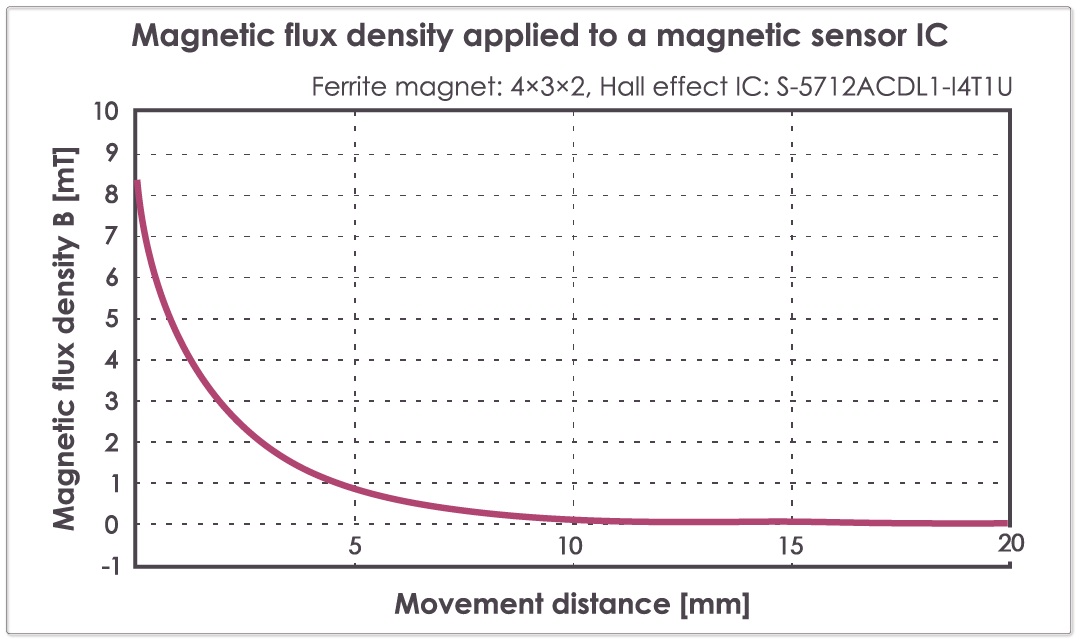
A magnetic field generated from magnets cannot be seen with the naked eye. A magnetic simulation is a technical method of visualizing invisible magnetism by quantifying the distribution and strength of the generated magnetic field. ABLIC’s magnetic simulation expresses the magnetism image in a curve or waveform graph, based on the mechanism operation that the customer is considering to adopt.
Applications Using Magnetic Sensor ICs
The following are examples of applications using magnetic sensor ICs.
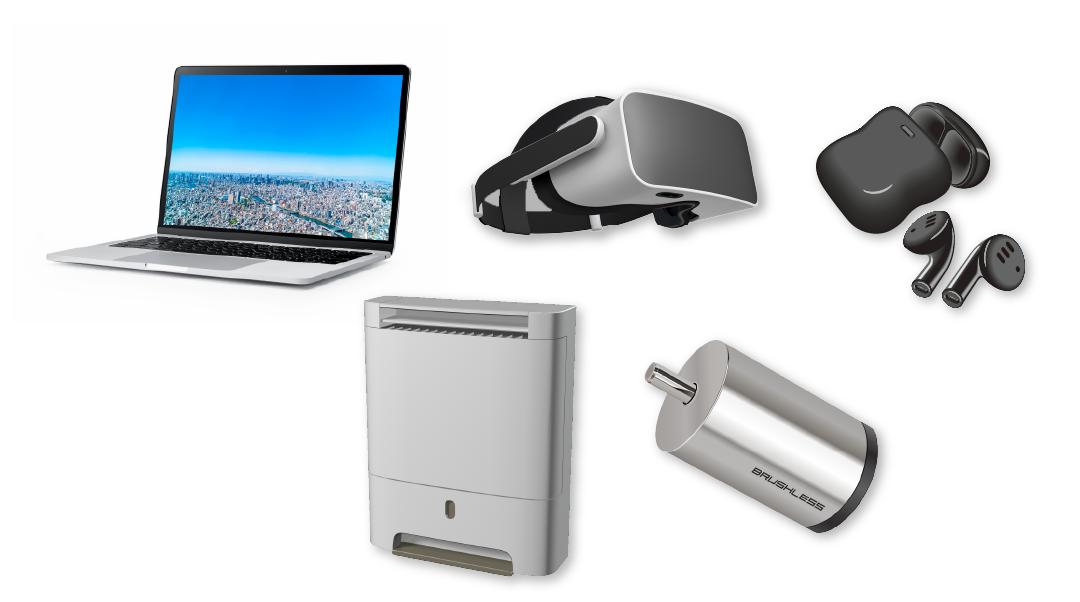
- Detection of open/closed covers: for laptops or mobile devices
- Detection of slide positions: such as the opening and closing of a window
- Detection of rotation: such as counting rotation of flow meters
- Water level detection (position detection): for water tanks within humidifying air purifiers, etc.
- Motor rotation control (rotation detection)
It can be observed that magnetic sensor ICs are now replacing traditionally used reed switches and mechanical switches within countless applications. Magnetic sensor ICs are already used in various applications such as automotive vehicles, industrial equipment, home automation, and electronic products.
Benefits of Using Magnetic Sensor ICs
- Resistant to mechanical vibration and impact
- High durability due to the non-contact method
- Resistant to humidity and corrosion
- Compact packages that do not restrict product design
- Applicable to various detection types due to its fast response time and wide selection range of magnetic sensitivity
- Does not affect battery life when using from a lineup of low-current consumption ICs
Why Is Magnetic Simulation Necessary?
In order to achieve reliable application functions, it is necessary to consider the magnetic field around the magnetic sensor IC in the mechanical design. During the design process, if the size/type/arrangement of the magnet is changed, the position of the magnet detected by the magnetic sensor IC will change - therefore, repeated prototype evaluations are necessary, resulting in the loss of a lot of time, effort, and cost. By using ABLIC’s magnetic simulation service, the customer can reduce the number of designs, prototypes, and man-hours, and confirm the target magnetic properties and operation results within a short period of time.
2. ABLIC's Magnetic Simulation Service
For customers using ABLIC's magnetic sensor ICs, we provide a magnetic simulation service upon request.
Based on the simulation results, customers can check rough operations with simple mechanism information, or complex operations with multiple magnets and ICs with 3D CAD data, as well as more detailed operations that take into account the influence of surrounding magnetic materials.
ABLIC has a lot of experience in providing precisely catered support in the past. If you are not satisfied with the detection or non-detection operation you are considering, we can propose the optimal IC, magnet, mounting position, etc. to reach your specific requirements.
How to Request ABLIC's Magnetic Simulation Service
When requesting the magnetic simulation service, mechanical information such as the detection method, magnet specifications, magnetic sensor ICs being used, as well as the position of the magnets, is required. There are two ways to make a request.
Battery Protection
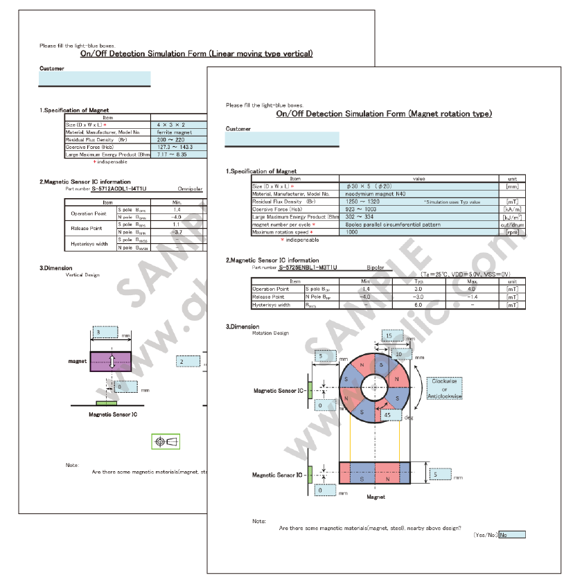
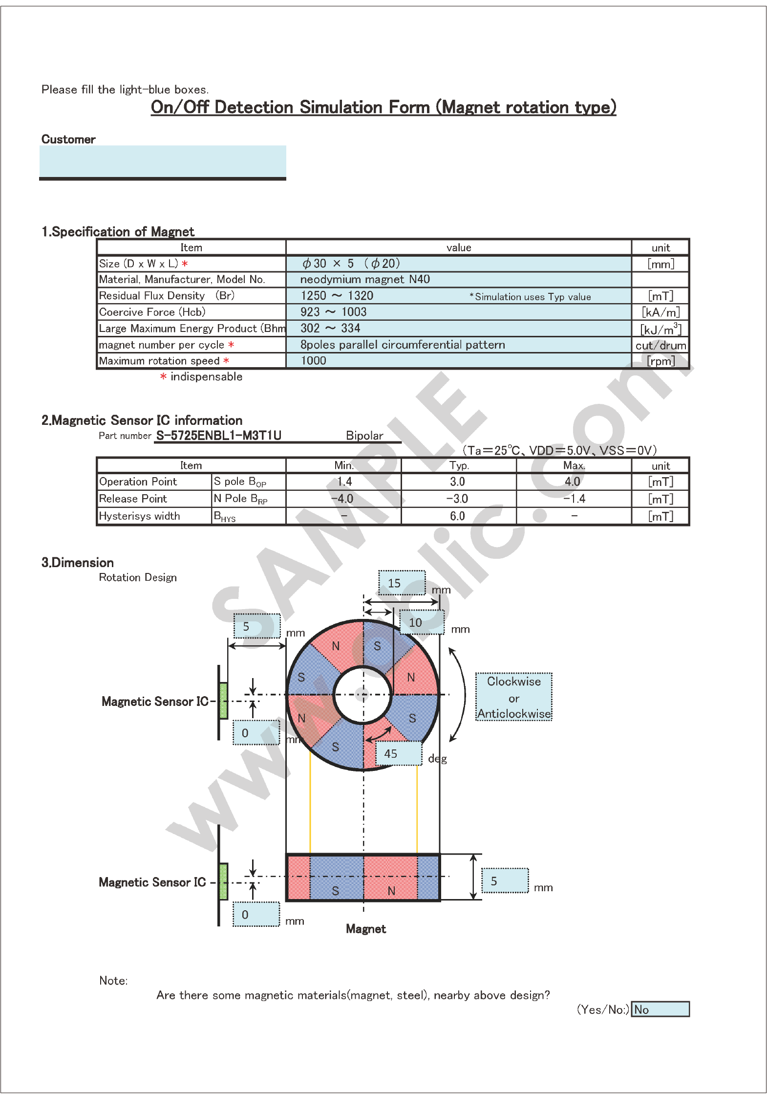
Filling out the request sheet according to the detection type is required. There are 5 types of request sheets: Linear moving type (parallel/vertical), circular moving type (arc/angle), and magnet rotation type.
Required information
- Specifications of the magnet used (size/type/known specs: Residual flux density Br/Coercive force Hcb/Large maximum energy product BHmax)
- ABLIC's magnetic sensor IC part number (S-57xxxxxx)
- The dimensions of the drawing depicted in the request sheet
- Mechanism motion information (if needed)
If confidential information is involved, it is also possible to sign a Non-Disclosure Agreement (NDA). For more details, contact our sales representatives.
Secondary Protection
If multiple magnets or magnetic sensor ICs are used, or if there are magnetic materials (e.g., steel) in the surroundings, we recommend requesting through 3D CAD data. The information required for requesting through 3D CAD data is as follows.
- 3D CAD data in the following formats
- STEP format (filename: .step, .stp)
- Parasolid format (filename: .x_t)
- Magnet information
- Explanation of magnet characteristics, magnetization direction and movement, etc.
- Additional information about magnet properties and shape (if needed)
- Surrounding steel information
- Steel material information (e.g., SUS304, SUS430, SPCC, or S45C, etc.)
- Additional information about steel shape and placement (if needed)
If confidential information is involved, it is also possible to sign a Non-Disclosure Agreement (NDA). For more details, contact our sales representatives.
Simulation Result Sample
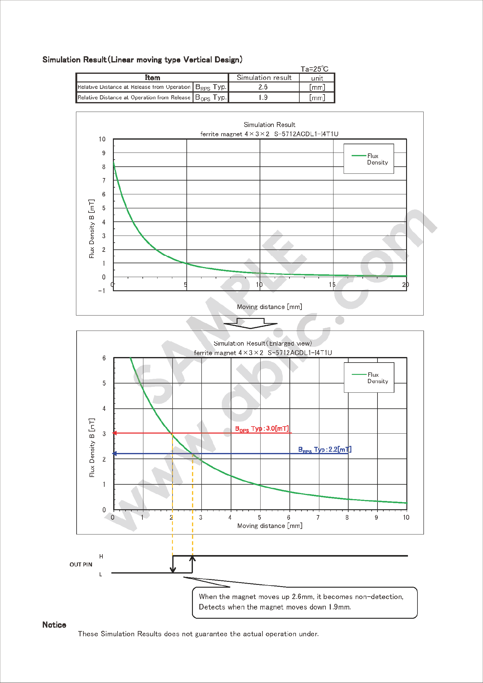
The simulation results are provided as a report including graphs as shown below, as well as the position (or angle) of the operation and release points* of the IC.
Result of magnetic simulation (linear moving type (parallel))
(Ta = 25°C)
| Item | Simulation Result [mm] | |
|---|---|---|
| Movement distance: close to open | BRPS Max. | 1.5 |
| BRPS Typ. | 2.6 | |
| BRPS Min. | 4.5 | |
| Movement distance: open to close | BOPS Max. | 1.3 |
| BOPS Typ. | 1.9 | |
| BOPS Min. | 3.8 | |
*Operation point (BOP): Position or angle when IC detects magnetic flux density.
Release point (BRP): Position or angle when IC no longer detects magnetic flux density.
Operation point and release point have a hysteresis width, so they are different values respectively.
3. Introduction of Actual Simulation Examples
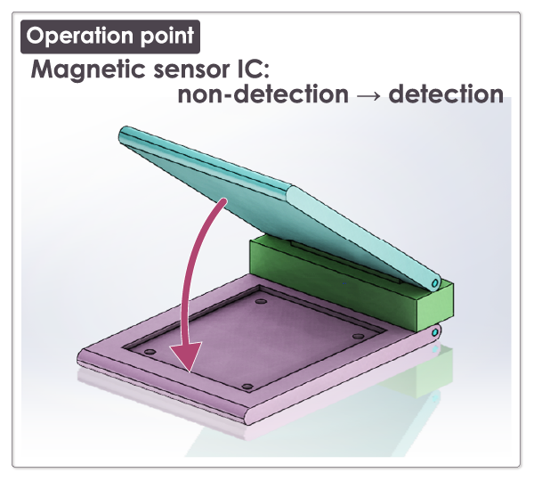
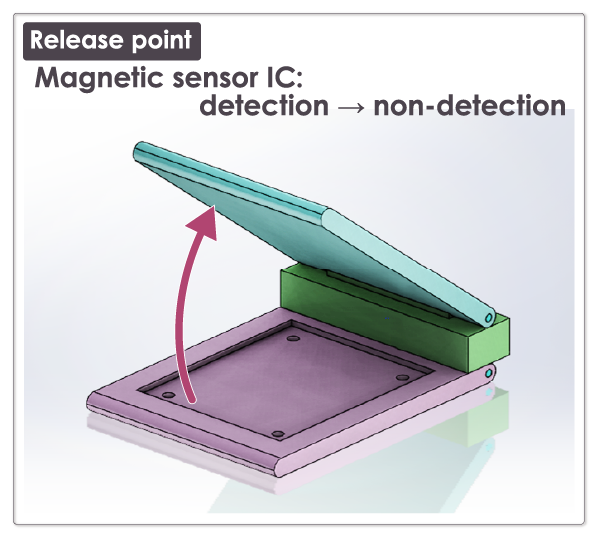
Open/Close Detection Using Magnetic Sensor IC
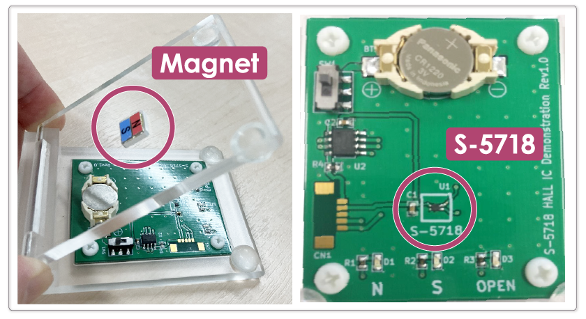
The following is an explanation of an example of magnetic simulation using an actual demo device (Fig. 1) that detects the open/close operation of the upper plate (lid) with a magnet.
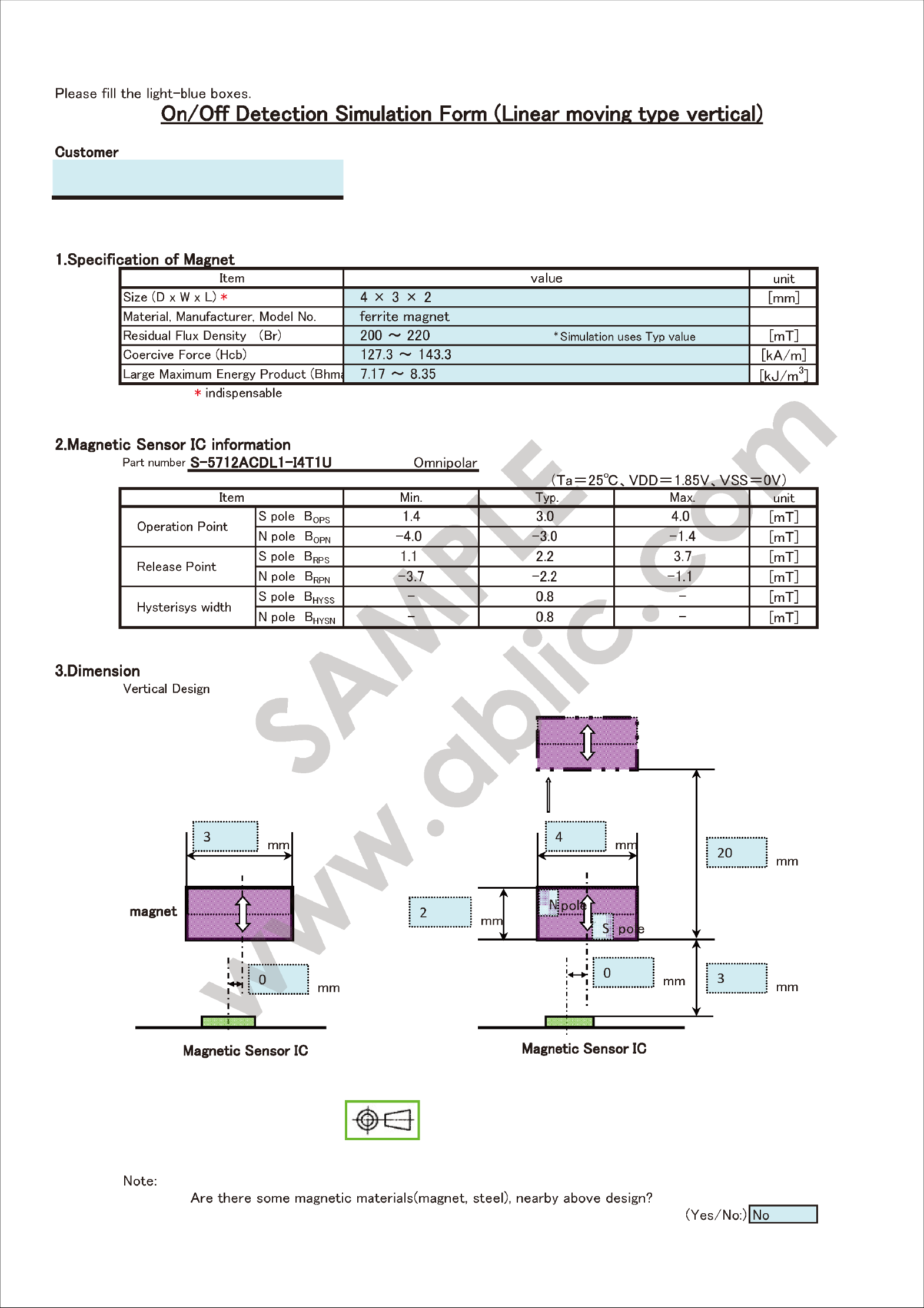
Description on the Request Sheet
The customer will fill in thebold frame .
Magnet Specifications
| Item | Value | Unit |
|---|---|---|
| Size (D × W × T) | 10 × 8 × 4 | [mm] |
| Material, Manufacturer, Part No. | Neodymium, N52 | – |
| Residual Flux Density Br* | 1450 | [mT] |
| Coercive Force Hcb | 979 | [kA/m] |
*In this simulation, the "residual flux density" of the magnet specification is used. If "surface flux density" is entered, the accuracy of the results may be reduced.
Magnetic Sensor IC Specifications
Part No.:
S-5718CCWL1-I4T1U, Omnipolar detection
(Ta = 25°C, VDD = 1.8V, VSS = 0V)
| Item | Min. | Typ. | Max. | Unit | |
|---|---|---|---|---|---|
| Operation Point | S pole BOPS | 1.6 | 3.0 | 4.0 | [mT] |
| N pole BOPN | -4.0 | -3.0 | -1.6 | [mT] | |
| Release Point | S pole BRPS | 0.5 | 1.7 | 2.8 | [mT] |
| N pole BRPN | -2.8 | -1.7 | -0.5 | [mT] | |
| Hysteresis Width | S pole BHYSS | – | 1.3 | – | [mT] |
| N pole BHYSN | – | 1.3 | – | [mT] | |
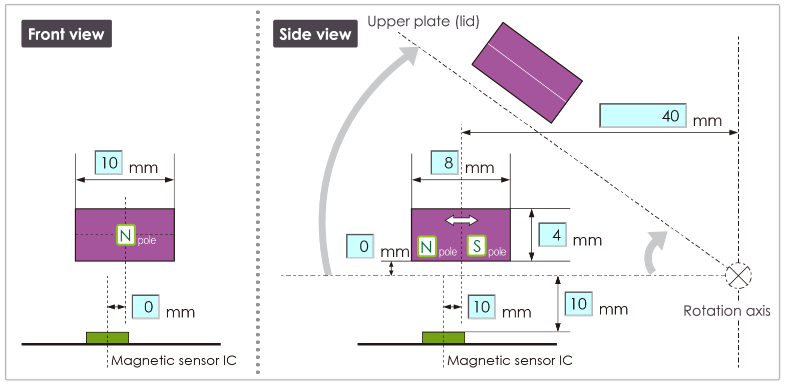
Parts Layout Information
The left side of Fig. 2 shows the positional relationship between the IC and the magnet from a front view perspective of the demo unit. The right side shows the positional relationship of the IC, magnet, rotation axis, etc. from a side view perspective.
The numbers inside thebold frame are used from the information for the simulation.
●Circular Moving Type (Angle)
Actual Simulation Result
The following is the result of a simulation based on the information listed on the request sheet.
Result of Magnetic Simulation (Numeric Value)
(Ta = 25°C)
| Item | Simulation Result [deg] | |
|---|---|---|
| Angle When Moving Operation point to Release Point | BRP Min. | 11.4 |
| BRP Typ. | 15.3 | |
| BRP Max. | 25.6 | |
| Angle When Moving Release Point to Operation Point | BOP Min. | 8.7 |
| BOP Typ. | 10.9 | |
| BOP Max. | 15.9 | |
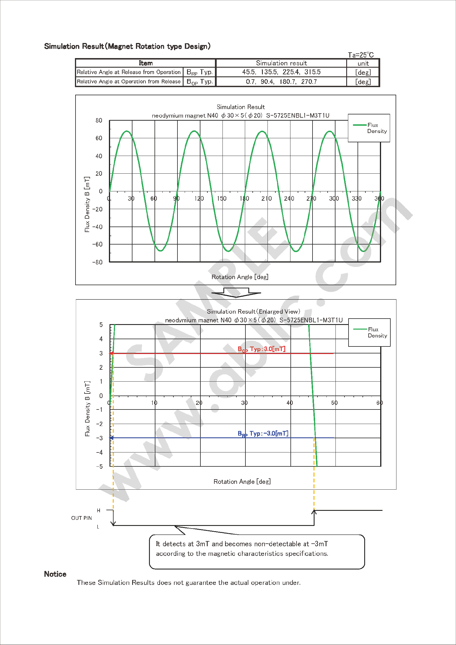
Result of Magnetic Simulation (Graph)


Result of Magnetic Simulation (Summary)
Release point → Operation point
(The angle at which the magnet is detected when closing the lid):
10.9° (typ.), 8.7 to 15.9°
Operation point → Release point
(The angle at which the detection status is released when opening the lid):
15.3° (typ.), 11.4 to 25.6°
4. Simulation Result Verification on Actual Demo Device
ABLIC verified the results of a simulation of open/close detection using a magnetic sensor IC with the demo device shown in Fig. 1. 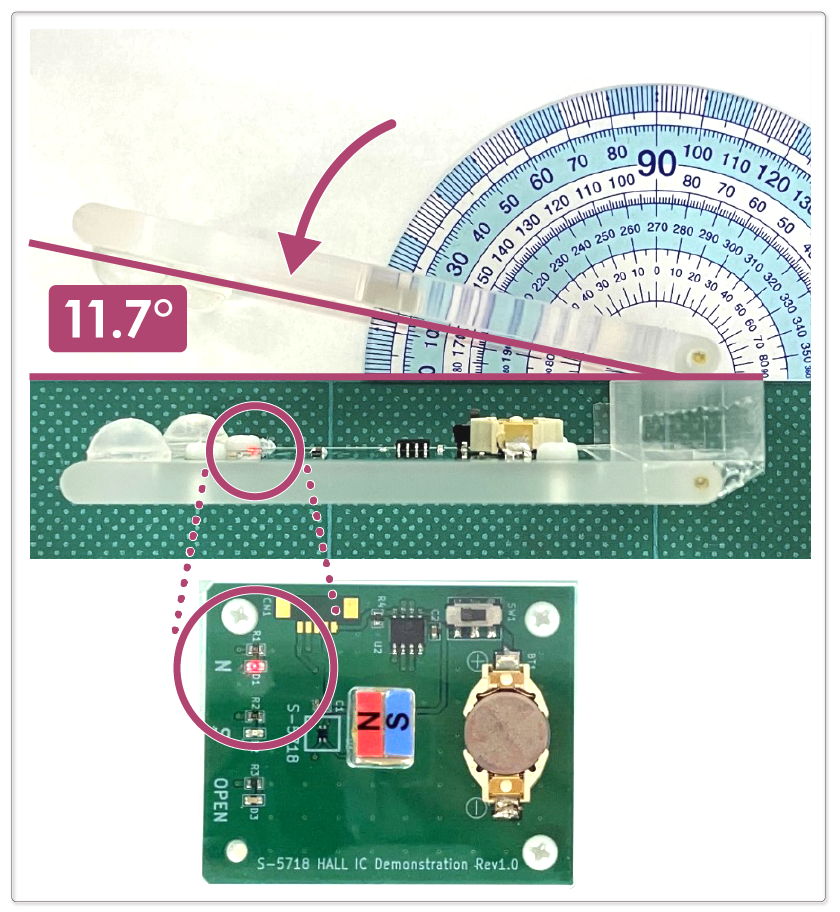
Fig. 4 shows the operation point when the lid is closed.
- Lid angle when the LED turns red: 11.7°
- Simulation result: 8.7 to 15.9° (10.9° typ.)
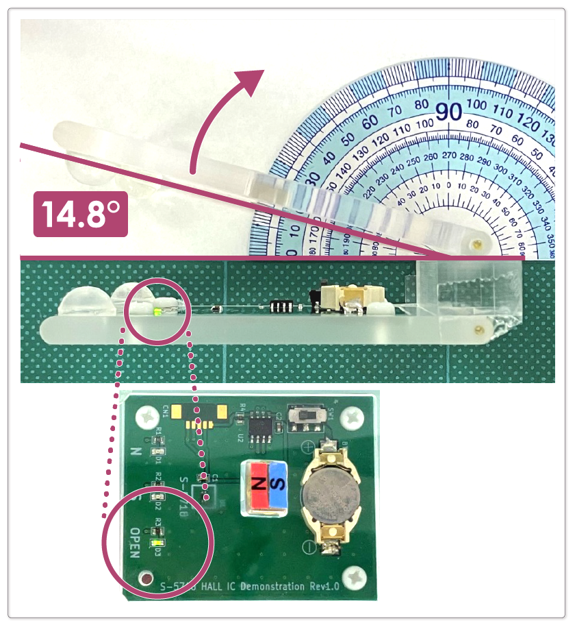
Fig. 5 shows the release point when the lid is opened.
- Lid angle when the LED changes from red to green: 14.8°
- Simulation result: 11.4 to 25.6° (15.3° typ.)
Based on the results above, it was confirmed that the actual measured values are within the simulation results and are similar to the typical values.
(Typical values are only a reference, as they are theoretical values that do not include the variation of sensor sensitivity, tolerances in mechanical dimensions, and the presence of surrounding magnetic materials.)
5. Use of ABLIC's Magnetic Simulation Service
In addition to the open/close movement of the lid that was introduced, it is also possible to simulate various detection operations such as the vertical movement of the magnetic sensor IC and magnet, and the ring magnet rotation movement detection.
Please feel free to contact our sales representatives about this magnetic simulation service or any questions.
Contact Our Sales Representatives
Battery Protection
Secondary Protection