Table of Contents
1. What Does the Actual Wireless Power Circuit Look Like?
By combining a transmission circuit that transmits the power, and a reception circuit that receives the power, wireless power transfer can be easily achieved.
The reception circuit can be divided into two types depending on the function: "a circuit capable of outputting a constant voltage", and "a circuit with a charge function used for small lithium-ion rechargeable batteries".
Transmission Circuit: Configuration
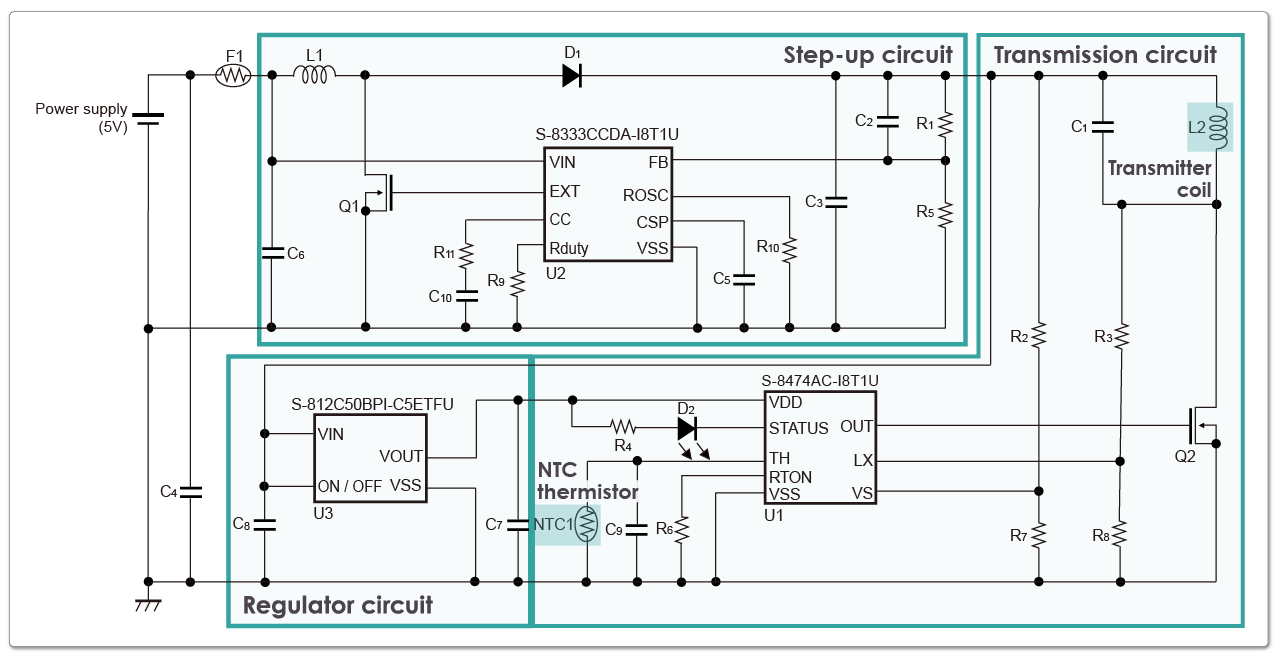
Figure 1 shows the configuration of the transmission circuit. This particular configuration is designed for a system supplied by a USB power source, so it consists of three circuits: a step-up circuit, a transmission circuit, and a regulator circuit.
- Step-up circuit:
boosts the 5V power supply to generate the required 9V voltage for transmission. - Transmission circuit:
controls the resonance of the transmitter coil by means of the transmitter control IC (S-8474). - Regulator circuit:
provides a stable power supply to the transmitter control IC (S-8474).
Transmission Circuit: Board Size
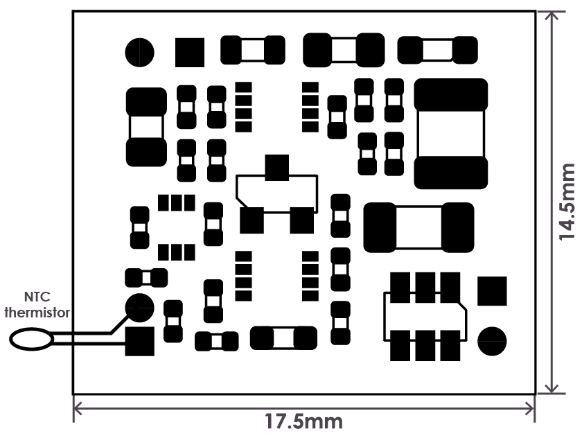
As seen in Figure 2, the 17.5mm × 14.5mm compact board size and an externally connected transmitter coil and NTC thermistor, enables the entire transmission circuit can be configured within this space.
Download document
S-8474 Series demo board user's manual
Reception Circuit: Configuration
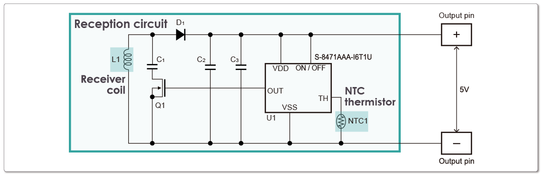
The reception circuit is a very simple configuration using only one receiver control IC (S-8471), as shown in Figure 3.
By aligning the transmitter coil from Figure 1 and the receiver coil from Figure 3 at an appropriate distance and achieving magnetic coupling, a constant 5V voltage is output from the output pin of the reception circuit.
Reception Circuit: Board Size
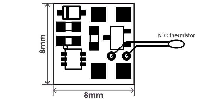
As shown in Figure 4, the reception circuit has a small number of components, and it can be configured on a smaller 8mm × 8mm board by simply connecting the receiver coil and NTC thermistor.
Download document | S-8471 Series demo board user's manual
Reception Circuit with Charge Function: Configuration
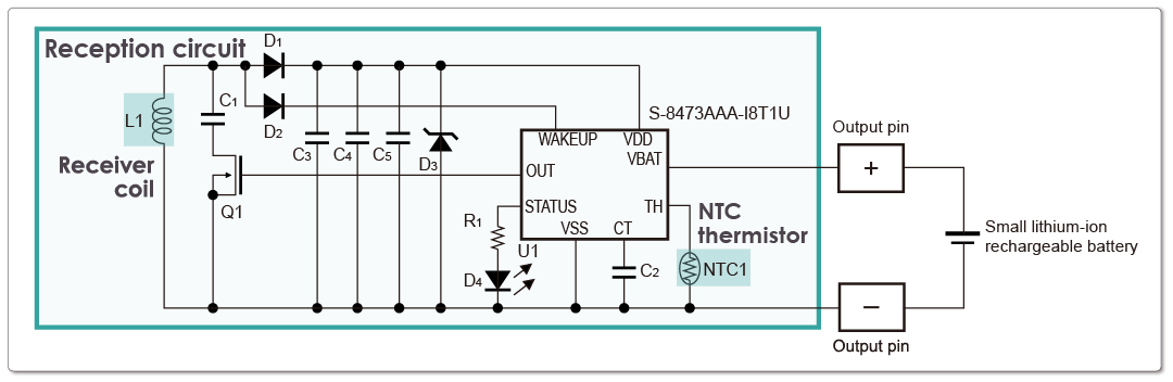
The reception circuit in Figure 5 is a circuit with a charge function for small lithium-ion rechargeable batteries.
This reception circuit also has a very simple configuration using only one receiver control IC (S-8473). By aligning the transmitter coil from Figure 1 and the receiver coil from Figure 5 at an appropriate distance and achieving magnetic coupling, the charging control of the small lithium-ion rechargeable battery connected to the output pin of the reception circuit is achieved.
Reception Circuit with Charge Function: Board Size
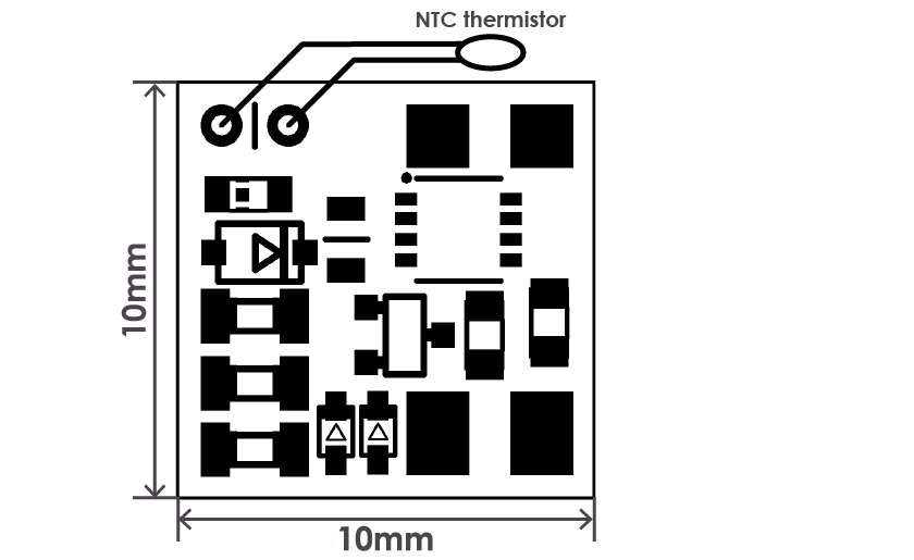
Since the charge current to the small lithium-ion rechargeable battery is relatively small, it is possible to miniaturize the components of the board. By simply connecting the receiver coil, NTC thermistor, and small lithium-ion rechargeable battery to a 10mm × 10mm board as shown in Figure 6, the entire reception circuit with a charge function can be configured.
Download document | S-8473 Series demo board user's manual
2. How Capable Is the Small Wireless Power Transfer?
Specifications and Functions
When using our recommended transmitter coil (φ20mm) and receiver coil (φ15mm), wireless power transfer can be achieved with a coil spacing of 3mm.
During this transmission, the maximum load current for the constant voltage output of 5V in the reception circuit shown in Figure 3 is approximately 100mA.
Additionally, the reception circuit with a charge function shown in Figure 5 performs constant current charging of 33mA to the small lithium-ion rechargeable battery and gradually reduces the charging current as it approaches full charge.
ABLIC's wireless power ICs can utilize a temperature protection function by externally connecting NTC thermistors to the transmitter and receiver sides.
Furthermore, the transmitter control IC (S-8474) and receiver control IC (S-8473) feature a status display function that uses LEDs to indicate temperature protection and charging operation.
Efficiency During Wireless Power Transfer
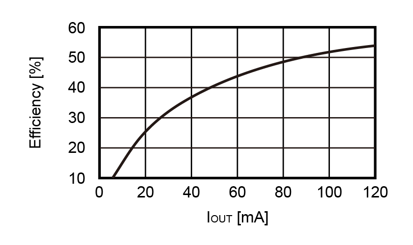
Figure 7 shows the efficiency during wireless power transfer using the transmitter control IC (S-8474) and receiver control IC (S-8471) without using step-up and regulator circuits within the transmission circuit when an external power source is used.
The efficiency exceeds 50% when the output current (IOUT) of the reception circuit is above 90mA.
Charging Characteristics of the Receiver Control IC (S-8473) with a Charge Function
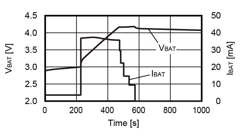
Figure 8 shows the charging characteristics during wireless power transfer of the receiver control IC (S-8473) with charge function for the small lithium-ion rechargeable battery. In this example, an electric double-layer capacitor is used as a substitute for the small lithium-ion rechargeable battery.
By performing constant current charging, the receiver control IC gradually lowers the charging current (IBAT) as the battery voltage (VBAT) also gradually increases and approaches full charge, resulting in the charge being completed.
3. A Video Demonstration of Wireless Power Transfer
A video Demonstration of Transmission Distance
The following video demonstrates the operation of power reception when the distance between the transmitter coil and the receiver coil is varied vertically from 2mm to 7mm.
It can be observed that the LED starts flickering when the coil spacing is 7mm, indicating that it is gradually moving away from the reception range.
(Play time: 1 min. 35 sec.)
A video Demonstration of Simultaneous Power Transfer to Multiple Receiver Units
The following video shows a demonstration in which multiple receiver modules are powered simultaneously using a single transmitter control IC.
In the video, as receiver modules are placed one by one on top of the transmitter coil, the input current on the transmitter side increases, and the LEDs on the receiver modules light up one by one.
(Play time: 1 min. 10 sec.)
Try ABLIC's Wireless Power ICs
| All S-8471/3/4 Series | Receiver control IC, Transmitter control IC | ― | |
| S-8471 Series | Receiver control IC | | |
| S-8473 Series | Receiver control IC with charge function | | |
| S-8474 Series | Transmitter control IC | |